
We produce multilayered flex and rigid printed circuit boards which are interconnecting layers which help our electronics engineers / design engineers to have the flexibility to use them as per their custom application / product design requirements which will also reduce cost.
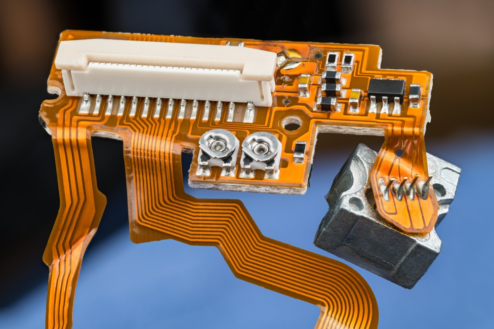
Rigid-flex PCB’s is not just ordinary flexible printed circuit board. It’s composition substrate lamination into single board that creates many opportunities and can also allow circuit board / electronic device manufacturing designers to find substitute of multiple printed circuit board interconnection with connectors, wires and ribbon cable to create a single printed circuit board with a view to improve overall performance, reliability and scalability in the process.

MNT Electronics brings tomorrow’s innovations today. Our consistent focus on innovation and developing new technologies is nurtured through continuous learning, excellence, distinction, investment and strong customer and supplier relationships. At MNT Electronics, we believe we possess what it takes to make us the ideal partner to provide electronics manufacturing, engineering and design services for your emerging technologies in mechatronics, green energy, and nanotechnology.
Printed Circuit Board Solution:
Benefits of Rigid Flex PCBs
Capabilities and Design Rules: Flex & Rigid Flex
| Description | Preferred | Standard |
|---|---|---|
| Number of Layers | 1 to 12 | 12 to 24 |
| Thickness Tolerance | +/- 10% | +/- 8% |
| Trace Width (mils) – 0.5 oz Copper | 5 and above | 3 to 4 |
| Trace Width (mils) – 1.0 oz Copper | 8 and above | 5 to 7 |
| Smallest Hole Size -Mech. Drilled | 10 mils | 8 mils |
| Smallest Hole Size -Laser Drilled | 4 mils | 2 mils |
| Aspect Ratio – PTH | 6:1 or Less | Up to 10:1 |
| Aspect Ratio – Blind Microvia | 0.5:1 | 0.75:1 |
| SMT Pitch (mils) | Over 14 | 6 to 14 |
| Impedance Control Tolerance | +/- 15% | +/- 10 % |
| Min. Pad Size – Int. (mils) | FHS + 22 | FHS + 18 |
| Min. Anti Pad Size (mils) | FHS + 32 | FHS + 26 |
| Min. Pad Size – Button Plate (mils) | FHS + 25 | FHS + 20 |
| Min. Pad Size – Pattern Plate (mils) | FHS + 22 | FHS + 18 |
| Min. Soldermask Clearance | 8 mils | 6 mils |
| Min. Soldermask Webbing | 8 mils | 6 mils |
| Min. Coverfilm Webbing | 14 mils | 10 mils |
| Covercoat Type | Coverfilm | Flex LPI |
| Allowable Squeeze out per Side | 5 mils/mil | 3 mils/mil |
| Trace Geometry | Curved | 45 degrees |
| “I-Beam” Traces | None | Minimal |
| Grain Direction | Specified | Longitudinal |
| Ground Plane | Cross-hatched | Perforation |
| Strain Relief | Yes | Yes |
| Inside Corner | Wide Radius | Radius |
| Construction Material | Balanced | Mixed |
| Bend Radius | Over 18x | 10x to 18x |